
In the early days of the commercial introduction of 3rd Gen AHSS, concerns with liquid metal embrittlement (LME) susceptibility emerged as the primary concern inhibiting the selection and use of these steels in automotive applications. In response, the Auto/Steel Partnership’s Joining Team developed a strategy to eliminate the potential of LME in the joining of 3rd Gen AHSS with emphasis on resistance spot welding.
The purpose of this article is to provide the reader with the Gleeble and the Rapid LME test procedures, the background needed to understand their origin, and a summary of lessons learned. It is hoped that this information will be useful in subsequent research and further improvements in reducing the potential of LME cracking in 3rd Gen AHSS joints, which will lead to increased application of 3rd Gen AHSS in meeting automotive OEM safety, performance, and sustainability targets.
It was already understood that a source of zinc (coating), a tensile stress and a susceptible material were needed for LME cracking to occur. There were conflicting reports on the LME susceptibility of 3rd Gen AHSS, but the preponderance of the evidence indicated that these grades were, in general, more susceptible than comparable strength AHSS. So, initial work focused on assessing the susceptibility of 3rd Gen AHSS as a function of coating and steel tensile strength.
Developing the Gleeble-based Test Procedure
There have been five phases of work in the last six years. The first phase of work focused on developing a laboratory test for assessing LME susceptibility. In the first phase, the Joining Team developed a test procedure using a Gleeble unit to dynamically simulate spot welding conditions and assess LME susceptibility of steel coupons as a function of temperature and strain rate. Table 1 provides example results for AHSS (DP590-GI) and 3rd Gen AHSS (3rd Gen 1180-GI) where the DP590-GI steel only showed LME cracking at higher temperatures, but the 3rd Gen 1180-GI steel showed extreme LME susceptibility at much lower temperatures approaching the melting point of zinc. LME susceptibility of each steel was subjectively rated either red, yellow, or green, which reflected the composite response of the steel over the range of temperatures and strain rates tested (see Figure 1). The test results revealed LME of 3rd Gen grades varied significantly between suppliers and that coating type (EG, GI, or GA) was not a significant variable. Unfortunately, the Gleeble test procedure was costly, time consuming, did not replicate the resistance spot welding process, and was qualitative. The Gleeble based LME test procedure can be obtained via this link.
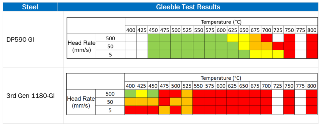
Table 1: Example Gleeble Test Results for DP590-GI and 3rd Gen 1180-GI steels.
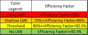
Figure 1: LME Severity Qualification
Developing the Rapid LME Test Procedure
The second phase focused on developing a quicker, lower cost test procedure that better replicated spot weld conditions. The new test, called the Rapid LME Test, applied a series of spot welds with increasing amperage followed by cross sectioning and metallurgical evaluation to assess the location (see Figure 2) and severity of LME cracks by location. Like the Gleeble test procedure, the Rapid LME test results were subjective since the location, number of cracks, and crack length varied significantly. Table 2 shows the processed results and weld cross sections (10 kA spot weld) for an LME susceptible steel (3rd Gen 1180-GI) and an LME resistant steel (3rd Gen 980-GI). The former is steel is the same 3rd Gen 1180-GI steel tested in Phase I. As with the Gleeble test procedure, the diverse cracking behavior in terms of location and severity made it difficult to quantify the LME susceptibility. The most successful approach to condensing the Rapid LME test results into a quantitative measurement of LME susceptibility was a weighted cracking index, which was useful in binning steels in terms of LME severity (severe, moderate, resistant) but was concluded to be too subjective. The Rapid LME test procedure can be obtained via this link.
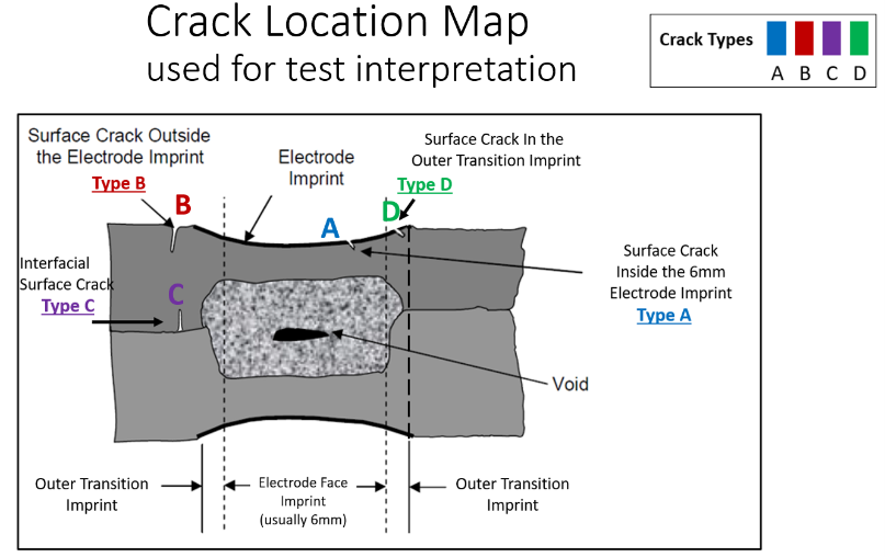
Figure 2: LME crack location map with respect to the weld electrode.
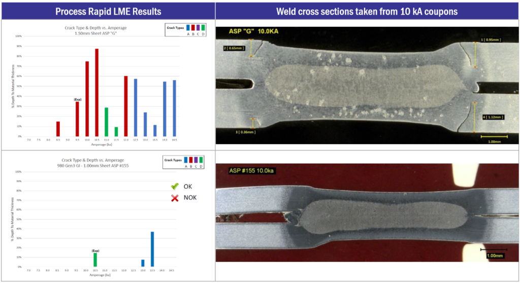
Table 2: Example LME Test Results for an LME susceptible 3rd Gen 1180 steel and an LME resistant 3rd Gen 980 steel Process Rapid LME Results Weld cross sections taken from 10 kA coupons.
The Rapid LME test results showed good correlation with the Gleeble test procedure results. Furthermore, the new procedure accomplished all three intended objectives, it took less time, was less costly and was more representative of the spot weld process. However, the procedure had only been applied to two thickness (2T) homogenous joints. Phase III was initiated to determine if the test could be used to qualify heterogenous joints of two or more thickness stack-ups.
The planned Phase III test matrix consisted of LME susceptible and LME resistant 3rd Gen AHSS spot welded to a thin CR4 steel in 2T and 3T joints. However, early 2T heterogenous testing revealed insufficient weld penetration into CR4 steel, which was attributed to differences in electrical resistivity between the CR4 steel and 3rd Gen AHSS (see Figure 3). A design of experiments was conducted to optimize the weld schedule and increase weld penetration sufficiently to meet automotive weld requirements. Although the DOE revealed a method to improve weld penetration, it confirmed a concern that process development was needed for heterogenous joints, which defeated the objective of having a simple test method with a standardized weld schedule. The Team concluded that the test could not be used as an LME joint qualification test but that it was still an effective test for determining material susceptibility to LME.
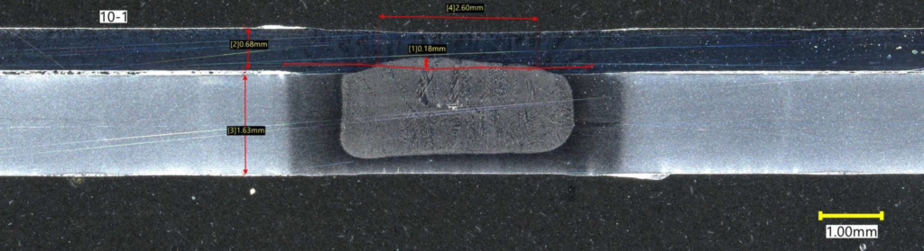
Figure 3: Example 2T Heterogenous Joint (CR4 on top / 3rd Gen AHSS on bottom).
Applicability and Future Work
Although neither the Gleeble nor the Rapid LME test procedures fully met the Joining Team’s objectives, the procedures were instrumental in enabling the Team to move from assessing LME susceptibility to developing strategies to mitigate the potential for LME cracking in automotive joints using 3rd Gen AHSS. Future articles will be provided that summarize the results of the work on developing an LME process map and techniques for developing LME resistant weld schedules. Furthermore, the Team is convinced that the results from the early LME testing were instrumental in leading to improvements in 3rd Gen AHSS formulations that are more resistant to LME cracking. Rapid improvements in resistance to LME cracking were observed from vendors whose initial submissions performed poorly but later submissions were remarkably improved.
Both test procedures are considered viable within identified limitations. The results from the Gleeble test procedure have been used for spot weld process modeling coupled with LME prediction. The Rapid LME test has been useful in assessing LME susceptibility, which is recommended before material selection and weld schedule process development. Additionally, the Rapid LME test results have been useful in developing an LME process map for 3rd Gen AHSS, and validating LME resistant weld schedules across a wide range of LME susceptibility. Subsequent articles will be published on the spot weld process model with LME prediction, the LME process map, and the work developing LME resistant weld schedules.